A Generic Brain Trauma Computer Framework to Assess Brain Injury Severity and Bridging Vein Rupture in Traumatic Falls-Juniper Publishers
Juniper Publishers-Open Access Journal of Head Neck & Spine Surgery
A Generic Brain Trauma Computer Framework to Assess Brain Injury Severity and Bridging Vein Rupture in Traumatic Falls
Abstract
Traumatic Brain Injuries (TBI) have been a major cause of morbidity and mortality for many years. The Organ Trauma Model (OTM) is a state of the art computer model, available to scientific community, which can calculate the threat to the life via white and grey matter brain injury severity level based on Peak Virtual Power (PVP), founded on the 2nd law of thermodynamics. The OTM model has however assumed, based on previous literature, that bridging veins rupture when the grey matter maximum principal strain exceeds 25.5%. This assumption does not permit to locate the vein tear as well as quantify the blood loss, which defines the injury severity. A 10-pair bridging vein shell computer model was devised, using published material properties and geometrical data connecting the grey matter to the dura, and defined a maximum principal strain to rupture of 15%. This bridging vein model was then tested in the case of a fall and correctly predicted the location of tear, as well as how many veins were damaged, suggesting that it is possible, with more validation cases, to link the number of damaged veins to the AIS level. This bridging vein model is a novel concept model which is showing a plausible response in direct linear impact and could be a good candidate for EuroNCAP pedestrian head strike against the vehicle, as well as helmet safety performance assessment. It has however not yet been validated in angular acceleration motions, hence more testing will be required in due course.
Keywords: Peak virtual power; Bridging veins; THUMS; Organ trauma model; Traumatic brain injuries
Abbreviations: TBI: Traumatic Brain Injuries; OTM: Organ Trauma Model; PVP: Peak Virtual Power; HIC: Head Injury Criteria; HPC: Head Injury Prediction Criterion; MPS: Maximum Principal Strain; AIS: Abbreviated Injury Scale; SDH: Subdural Hematoma; SPH: Smooth Particle Hydrodynamic
Introduction
Traumatic Brain Injuries (TBI) have been a major cause of morbidity and mortality for many years, and a major systematic review was conducted in 2005 [1], which is still one of the best collected references on the subject. In Southern Europe, road traffic crashes constitute the vast majority of cases, while falls related to alcohol consumption are the leading cause of trauma in Northern Europe [2]. Head trauma accounts for most deaths seen in trauma centres [3] with some researchers predicting that road traffic crash-related injuries will increase from ninth to third in the world disease burden ranking [4].
Another review by Post et al. [5] gives a highly detailed account of the history of assessing TBI evolving from the Wayne State Curve in the early 50’s, through the Gadd Index leading to the Head Injury Criteria (HIC) in the US [6] and the Head Injury Prediction Criterion (HPC) in Europe [7]. There are several papers on TBI which mention falls, however, there are few that analyse head injury and compare the results to the real world. Some studies have used also Multi-Body Models which are good for kinematics but not so good for injuries [8-10]. Other studies [11,12] use detailed FE model and classical means of determining fall velocities. They output their results against a range of mechanical parameters such as the von Mises stress, or Maximum Principal Strain (MPS) and show reasonable correlation; however, they could not assess the injury severity.
Medical professionals have defined real-life injury severity through the establishment of a trauma injury scale known as the Abbreviated Injury Scale (AIS) [13]. The AIS is internationally accepted and is the primary tool to conclude injury severity and is anatomically based. It has been derived by consensus as a global severity scoring system that classifies each injury by body region according to its relative importance (threat to life) on a 6-point ordinal scale, it provides a standardized terminology to describe injuries and it ranks injuries by severity (Table 1) [13].

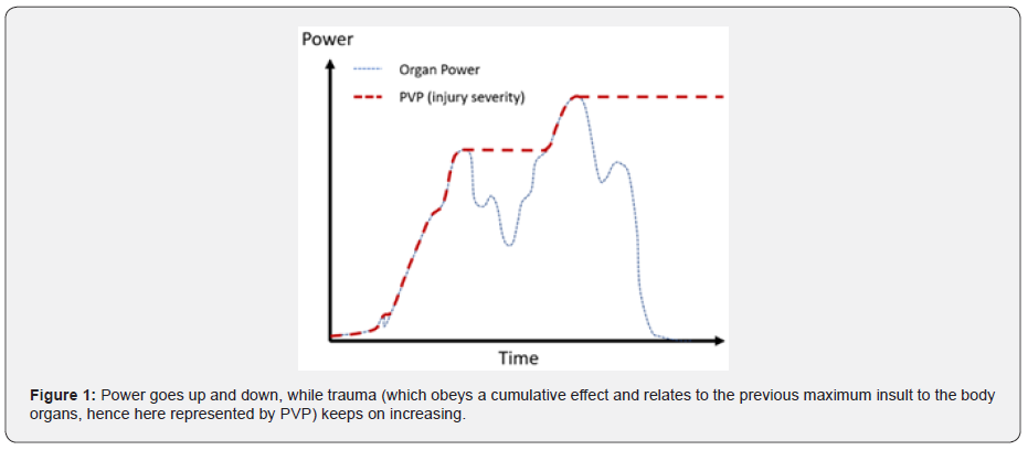
Some initial work by the authors have investigated brain injuries in pedestrian-to-vehicle collisions [14] using a concept called Peak Virtual Power (PVP). PVP is based on the general principle of the 2nd law of thermodynamics, stating that entropy (state of disorder) increases after each mechanical process [15-17]. When a collision takes place, the entropy (represented by PVP) always increases, never to return. A typical pattern of this behaviour is illustrated in (Figure 1), power (energy input per unit time) goes up and down, while PVP stays at the previous maximum value of power throughout, PVP being also proportional to the maximum rate of Entropy production.
It is assumed that the Damage Tensor is proportional to Injury Severity or AIS [15]. The general PVP formulation is provided in (Equation 1). The full derivation and application to a fall have been published [18], taking into account ageing effects (brain shrinkage and material properties degeneration), as well as the stiffness of the impacted surface. PVP is function of the impact velocity.
Equation 1: PVP general equation
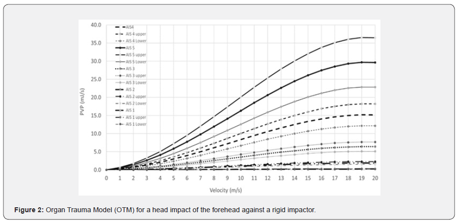
This method has been shown that it is possible to compute the white and grey matter injury severity in a fall, using the THUMS 4.01 human head model [19], by calibrating the PVP necessary to reach the maximum MPS value in those areas of interest in the brain (Table 2) [20,21]. Once this maximum power value for a specific AIS value is known, it is possible to interpolate all the other AIS values [14], as illustrated in (Figure 2).

This previous study, however, had to estimate the state of brain bleeding. The THUMS 4.01 finite element model is built on contact volume elements, hence no volume loss due to blood loss can be accounted for as part of the calculations. To factor in, and include the bleeding effect, one has then to include the effects of Subdural Hematoma (SDH), which has been defined as occurring for an MPS value of 25.5% [22] on the surface of the grey matter elements. This added implementation is convenient, however it has little relationship with the real brain biomechanics, as bleeding is actually caused by rupture of bridging veins, which are missing in the THUMS model. Upon reaching this critical MPS threshold, the AIS predicted by using PVP was augmented by ‘1’ for a small bleed, or by ‘2’ if the bleeding is judged to be important by the pathologist [23].
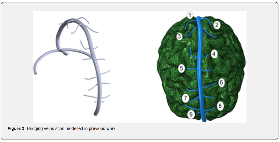
The problem with this method is that the AIS shift depends on the subjective observation of the pathologist and can only be known posteriori. Consequently, the inclusion of a bridging vein into the previous work is therefore necessary. Very few bridging vein models exist. The most detailed one has been developed and validated based on a CT-Scan, then converted into a CAD model for meshing, analysis and validation [24,25], as illustrated in (Figure 3).
This model is admittedly, somewhat patient specific, because of the precise location of the veins and some geometrical features (such as diameter, wall thickness etc.). Furthermore, the veins were modelled with second order solid elements, which preclude its further potential to allow it to be parametrized (shape, size, and location) for adapting it to other patients, or for performing variation studies. This solid finite element model will be analysed in detail in the methodology section and will be used as the reference to build later on a simplified bridging vein model, which will have comparable responses in a fall. The damage observed in this simplified bridging vein model will be compared to the Postmortem report.
Materials and Methods
The methodology used will consist of three steps. The first one is to investigate the bridging veins material properties, then the finite element modelling strategies, followed finally by a validation in the THUMS 4.01 head model (adjusted for brain shrinking and brain white and grey matter properties) in a fall scenario.
Bridging veins material properties, geometry and current models
Bridging veins vary in geometry and stiffness. A major work [25] summarized in (Table 3), has shown that bridging veins material properties, on average, did not vary considerably in stiffness across strain rate variation up to 200/s (23.26MPa to 28.13MPa). (Table 3) does not suggest any adjustments for ageing. The range within which the material properties vary suggests that it may not be possible to obtain a definitive bridging vein response, however it will be possible provide a bound for their responses.

Although many authors theoretically report that bridging veins may have a hyperelastic behaviour [26], other experimental studies support the proposition that bridging veins behave as an elastoplastic material [25]. Some CAE models have been developed to model bridging veins [27] by using elastoplastic material behaviour, including failure onset. When considering bridging vein responses, it can be observed that their average response is linear [25,27] until the point when the onset of a tear appears. Some correlation has been undertaken (5mm long bridging vein with a diameter on 1.5mm and a 0.044mm wall thickness), using the ‘All’ field from (Table 3) and a Poisson’s ratio of 0.45 representing a logical uncompressible behaviour for the vein material, and have matched the same failure strain as the tests [27].
Even if these values are specific, they are plausible values within the range provided in the literature [25,26,28-32]. This computer model provided a probable indication for the failure strain to be 0.31875 (value input in the material law as cut-off strain value to match the correlation), comparable to standard values obtained from (Table 3). An important point to note is that the bridging vein response is linear and not strain rate sensitive. Consequently, a simple linear material property model would be adequate. With the current material model used, some potential problems could become apparent in compression, where negative volumes could present themselves.
Another concern is the applicability and deployment of a material model which uses second order solid elements. Industrial applications, like transport safety analysis, use first order finite element formulations with a fully integrated solution for increased accuracy. The authors challenge the need to use 3D solids elements, as shells, especially if they are thin, are accurate and more efficient. Indeed, it is possible in a shell to add integration points across the thickness, so that any stress pattern across the thickness can be captured without the numerical cost of solid elements where good practice stipulates that at least 3 elements through the solid thickness are required to capture the stress pattern accurately [33]. Finally, a comment of the modelling strategy is that the elements in the correlation model are in tension, hence there no risk of stability issues, but on the other hand one wonders whether the model will be stable when the load is reversed.
Finite element strategies
As the material response is linear over a large range of strain rates and that the bridging vein is shaped like a tube, it is proposed to investigate different meshing strategies which will be tested against the trauma outcome evidenced in a fall case. As explained above, solid meshing approaches will not be considered.
Springs and rods
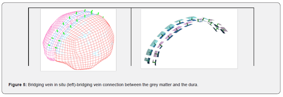
The bridging veins are connected to the dura and the grey matter and have no bending stiffness; hence they could be modelled with simple springs or rods, linking nodes between the grey matter and the dura. It is therefore possible to locate them in comparable positions as illustrated in (Figure 3). The number of bridging veins and location differ from person to person. Some similar attempt was performed in 2007 at KTH [34], using linear springs with a stiffness on 1.9N/mm. The authors are challenging this spring stiffness whose stiffness is provided by (Equation 2), returning a typical value of 9N/mm, based on an average 5mm length bridging vein and average property from (Table 3). The KTH model spring stiffness is four times stiffer than what is mechanically expected, hence not suitable for studying overall responses of bridging veins.
Equation 2: Stiffness of spring or rod
Subsequent models, like the SIMon model [35], containing 11 pairs of bridging veins, used cable discrete beams with a Young’s Modulus of 0.275MPa [36]. Such models are useful, however the mechanical properties used do not relate to the Young’s Modulus values in (Table 3), hence it cannot be used as a specific predictive model. Furthermore, the number of bridging veins (showing in Figure 3) appear to also be patient specific, as other previous work only scanned 9 pairs and not 11. The authors here propose an arbitrary 10 pairs of bridging veins network with the spacing between veins varying between 16mm and 24mm. This spacing was decided to align with the pre-existing mesh provided in THUMS 4.01.
Springs and rod models, using the mechanical properties from (Table 3), were tested and returned both the same answer. For simplicity of post-processing, the authors chose the rod model, whose strain response can be extracted from the normal force divided by Young’s Modulus and the rod’s cross section and is not dependent of the specific length of each element (as per the spring elements).
Shell elements
As per the Simon model, which uses cable elements to resist in tension and become ‘slack’ in compression, it is proposed to use a similar methodology by utilizing a FABRIC material, with linear responses (strain rate effects are not important) with the same warp and weft properties being chosen. The geometry of the bridging vein is illustrated in (Figure 4), with the X and Y axis being the warp and weft directions along the surface of the vein.
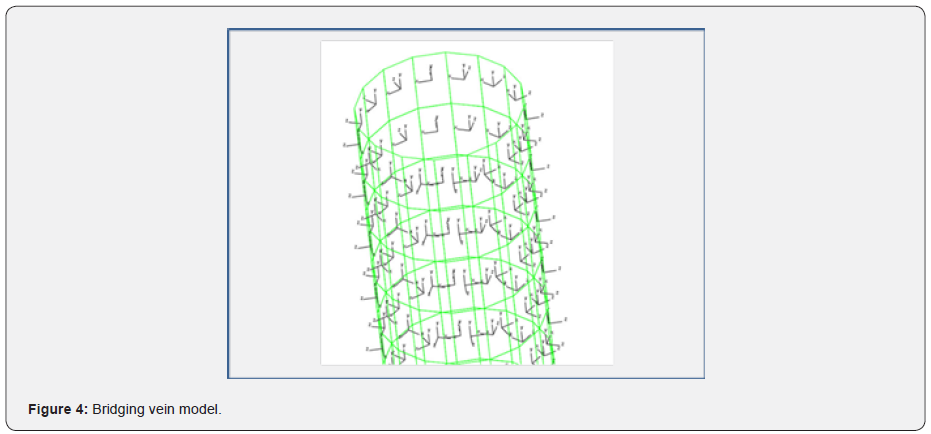
The underpinning for the meshing dimensions can be found in the Appendix. The bridging veins are positioned between the grey matter and dura. The nodes situated at both extremities are selected and added into a TIED_CONTACT so that any relative motion between the grey matter and the dura will influence the stretch of the bridging veins as they are connected, as illustrated in (Figure 5).
Fall load cases and damage criteria
The research will revisit a previous study, in which the sequence of events is paraphrased by the original authors as: “A 63-year-old male was slightly pushed leading to him taking two steps backward, stop and then fall backwards like a stick, and thus sustaining a parieto-occipital head impact on the wooden floor. This event was witnessed by ten people who all gave the same version of the fall. During transportation, the male fell from the stretcher from a height of about 20-30 cm on his right hand side, sustaining a parietal head impact” (Table 4) [11].

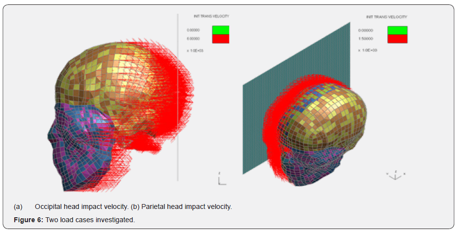
The two load cases in which the new bridging vein models have been included, were modelled in LS_Dyna, are shown in (Figure 6). Some detailed CAD modelling of the bridging veins was undertaken, and the model tested against various load cases [24], setting the maximum principal strain to 31%. These have led to a tear at the junction between the dura and the bridging veins, as illustrated in (Figure 7). This is well captured numerically as the geometry is accurate as well as the solving method which is based on a second order element formulation.
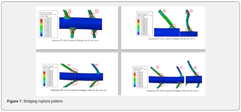
The modelling method chosen in this paper is a simplification of (Figure 7), hence the rupture location will not be captured, as the radii have been omitted. It can however be observed that the onset of the tear occurs when the maximum principal strain in the central bridging vein exceeds 15%. Hence it is possible to set this level as a plausible failure strain in the cylindrical bridging vein shell model. This value is reasonable as it is comparable to the elastic strain threshold which is set around 12% (Table 3) and 16% to18% as lower thresholds for bridging veins rupture. Both modelling techniques will be compared against this threshold value as well as the PM outcome provided for the two falls as criteria for deciding whether this cylindrical bridging vein model is in principle acceptable.
Results
Rods 6.0 m/s
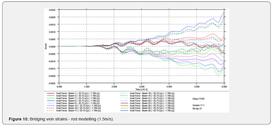
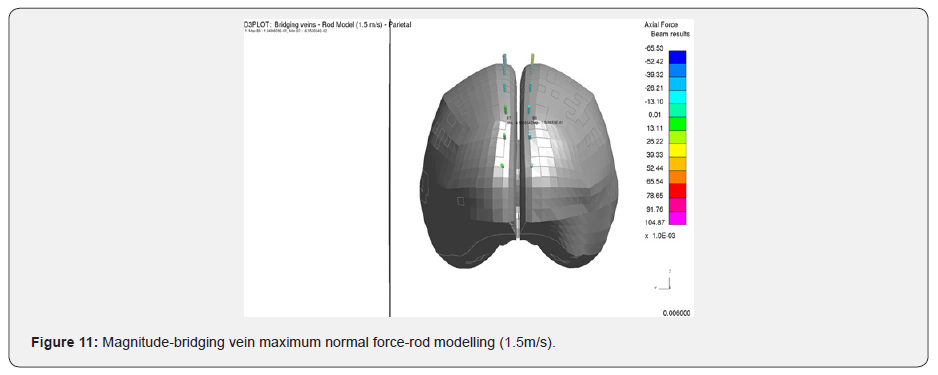
(Figure 8-11)

Shell Elements 6.0m/s


(Figure 12 & 13)
Shell Element 1.5m/s
(Figure 14 & 15)
Discussion
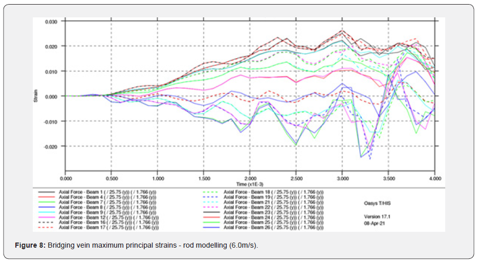
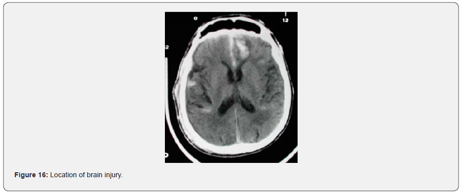
It can be observed that the strain level between the rods and the shells vary greatly, the rods being the lowest. This is expected as the rods have a restricted number of degrees of freedom, i.e. only able to stretch along their length. The shell model, on the other hand, is more flexible, hence it generates higher strains levels. What is consistent is the strain pattern between these two models, each predict higher strains in the frontal area on the bridging veins, as when the skull stops, the brain keeps moving, rotating about the contact area between the skull and the plate. This is illustrated clearly in (Figure 13), as well as being validated from the CT-Scan from the victim (Figure 16) [11].
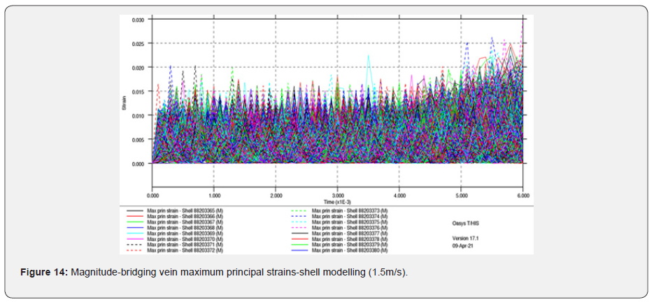



What is remarkable it that the rod model’s strains are under the threshold of 15%, which is necessary to capture the onset of bridging vein tear, while the shell model does exceed that maximum principal strain level. The rod model’s response could, of course, be calibrated to compensate for its reduced degree of freedom. However, the relationship between this calibration and the physical material properties would have no meaning should either material ageing, different bridging veins diameters and maybe different range of material properties be incorporated in the model later for investigations. In the case of the parietal fall, no injuries have been observed (Table 4), which is also observed in the MPS values recorded in the shell model, which are around 3%, again well below the 15% threshold target defined in this research.
In the case of the 6.0m/s occipital fall, grey matter contusion is calculated as AIS 3 (serious injury, red dot in Figure 17) using (Equation 1) and the bridging vein rupture AIS4+ (black dots). It can be proposed, that according to the number of veins torn, the AIS prediction level (4 or 5) could be adjusted accordingly. This is an improvement from previous research which was suggesting to add +1 or +2 to the grey matter should the MPS in the grey matter exceed 25.5%.
In (Figure 6 & 8) bridging veins are completely torn, as most of the elements exceed 15% MPS. Overall, 12 bridging veins have at least one element exceeding 15% MPS (out of 22). It could therefore be proposed that a large number of veins are damaged, hence it would suggest AIS 5. For this matter, more cases need to be investigated to confirm this hypothesis. This result matches the Postmortem report (Table 4), as the overall grey matter AIS outcome is AIS4+, represented in a range in (Figure 17).
In the case of the 6.0m/s occipital fall, white matter contusion is calculated as AIS 4 (severe injury, red dot in Figure 18), which is again compatible with the findings in the post-mortem report (Table 4). In the case of parietal fall at 1.5m/s [18], no DAI and contusion injuries were observed using the PVP theory from Equation 1, nor any bridging vein rupture, which again ties up with the post-mortem findings.
When considering these two fall cases, and comparing the shell model tear response, it can be concluded that our present proposed model is suitable for direct impact cases. It must be noted that this model has not been tested for angular/ rotational accelerations, hence no conclusions can be drawn if this model can be used in such scenarios. It could be envisaged that this model could be a candidate to model motorcycle helmets head injury performance, in which the head form impactor is simply dropped vertically against a rigid block.
Conclusion
A cylindrical bridging vein computer model is proposed to improve the prediction of bridging veins brain damage, as well as completing the framework of a generic brain injury severity trauma model. Previous work permitted the computation of the injury severity on the white matter (diffuse axon injuries) and the grey matter (brain contusion). However bridging vein bleeding was only evaluated when in grey matter the maximum principal strain exceeded 25.5%. This metrics seems to hold true in our study, however with in this previous method, the bridging vein rupture location as well as the number of veins damaged could not be evaluated.
The present study remedies these limitations and proposes a new bridging vein finite element shell model based on fabric material model with a linear response, as it has been evidenced in physical tests in the literature, that bridging veins were not sensitive to strain rate. The rupture level was calibrated against previous finite element work and material physical test data where the rupture was evidenced. From this work, it was concluded that a maximum principal strain of 15% was a plausible threshold level to capture bridging vein rupture. In the fall case studied, it was possible to extract and verify, with the help of a CT-Scan image, the location in the brain where bridging veins were torn.
A study within this paper has also investigated whether bridging veins could also be modelled as rods. It was concluded that even if the location of the bridging vein damage was comparable to the shell model’s response, the maximum principal strain to the rupture level for rod elements had no bearing with the material natural response due to their reduced degree of freedom. Consequently, rod, spring and cable bridging vein models are too limited and cannot be used for advanced research, which needs to account for material and dimension variations which are usually observed in biological tissues.
This new bridging vein model has allowed to refine the trauma model based on peak virtual power and has provided a potential technique to provide the AIS level evidenced during bridging vein rupture simply by investigating how many veins have exceeded the rupture limit. The present bridging vein model is a proof-of-concept model which is showing a plausible response in direct linear impact and could be a good candidate for EuroNCAP pedestrian head strike against the vehicle, as well as helmet safety performance assessment. It has however not yet been validated in complex motions, which include angular accelerations, and consequently more testing will be required in due course.
Further Work
The bridging vein computer model proposed in this paper does not have any blood flow inside its volume. Future work will therefore investigate whether the addition of smooth particle hydrodynamic (SPH) fluid particles, or a non-Newtonian fluid model inside the shell model volume will affect the rupture response. More cases will be investigated to link the brain AIS level with the number of bridging veins ruptured.
For more articles in Open access Journal of Head Neck & Spine Surgery | please click on: https://juniperpublishers.com/jhnss/index.php
For more about Juniper Publishers | please click on: https://juniperpublishers.com/pdf/Peer-Review-System.pdf


Comments
Post a Comment